
Sustainable Control Cabinet Cooling and Operational Safety - A Contradiction?
Experts for control cabinet cooling from the IGTE (Institute for Building Energy, Thermotechnology, and Energy Storage) at the University of Stuttgart and Friedrich Lütze GmbH are repeatedly confronted with the conflict between sustainable resource use and operational safety.
A variety of factors must be considered for a holistic assessment of the CO2 footprint caused by a control cabinet and system operation. In direct connection with control cabinet cooling, these include the electricity used for cooling, the production-related CO2 footprint of the installed cooling technology, any refrigerants used with high greenhouse potential, decommissioning and recycling costs, as well as retrofit or replacement costs due to premature component failure. The issue of energy consumption is particularly relevant because it can be quantified most easily among the mentioned influencing factors.
Energy efficiency in the industry is essential
In 2021, about 0.42 kg CO2 per kWh of electricity generated was produced in the German electricity mix. Even though the emissions factor in Germany is expected to decrease further in the coming years due to the progress of the energy transition, it is not expected that green electricity will be widely available in the short to medium term due to the current geopolitical situation. This makes energy efficiency improvements in the industry essential.
Control cabinets must be actively cooled above a threshold value of the thermal power released during operation to achieve a target average indoor temperature, as determined by the laws of thermodynamics. This threshold value is an individually determinable characteristic for each control cabinet and depends, in particular, on the target indoor temperature itself, the maximum expected ambient temperature, and the spatial dimensions of the control cabinet. However, in practice, hotspots can still form around components with high specific power dissipation, even with an installed and correctly sized cooling device, if they are placed in dead zones, for example.
Theoretical Consideration as Basis
In cooperation with the IGTE of the University of Stuttgart, Friedrich Lütze GmbH has been working on the topic of thermodynamics in control cabinets for more than 12 years. A crucial aspect of optimizing the climate in control cabinets is the theoretical consideration using simulation models. Based on the experience gained through years of research, practical measurements, and the developed models, Lütze created the AirTEMP calculation program. Unlike conventional calculation programs for sizing control cabinets, AirTEMP divides the control cabinet into several subzones, and the flow situation that results from the chosen cooling concept is individually considered. To further develop the underlying simulation model, impulses from practice and collecting measurement data are of central importance. The significance of an individual thermal control cabinet analysis is particularly evident in the case of control cabinet combinations without separating inner walls. Sufficiently dimensioning a cooling device and placing it on a control cabinet combination alone is not a guarantee for trouble-free control cabinet operation. This is vividly illustrated by a practical measurement conducted by the authors.
Measurement in Practice
Two control cabinets from a control cabinet combination were considered. Both control cabinets were equipped with the LÜTZE AirSTREAM wiring system. Control cabinet A (drive cabinet) had a front-mounting cooling device, and the adjacent control cabinet S (control cabinet) was not actively cooled at the beginning of the investigation (free cooling). Ten temperature sensors were placed on temperature-sensitive components and in the free air volume (detection of air layering) for each control cabinet. The maximum and minimum temperatures recorded over a production day are visualized in Figure 1, distinguishing between Control cabinet A (cooling device) and Control cabinet S (no cooling). It is noticeable that maximum temperatures of about 38 °C occur in Control cabinet A. Here, the cooling device prevents the occurrence of inadmissibly high temperatures. However, the situation is different in the adjacent Control cabinet S. The theoretical consideration during system planning may have been that the cold air introduced into the adjacent control cabinet by the cooling device would be distributed throughout the control cabinet combination. The measured values demonstrate that this is not the case. Temperatures of up to 53 °C occur in Control cabinet S. This is too high for sensitive control components and can lead to a reduction in their service life in the long term. Furthermore, it is noticeable that there is sometimes a temperature stratification of more than 20 K in control cabinet S. In order to reduce the maximum temperature in control cabinet S to below the target value of 40 °C with the existing cooling concept, disproportionately more cooling power would have to be introduced into cabinet A.
Control cabinet drive (cooler)
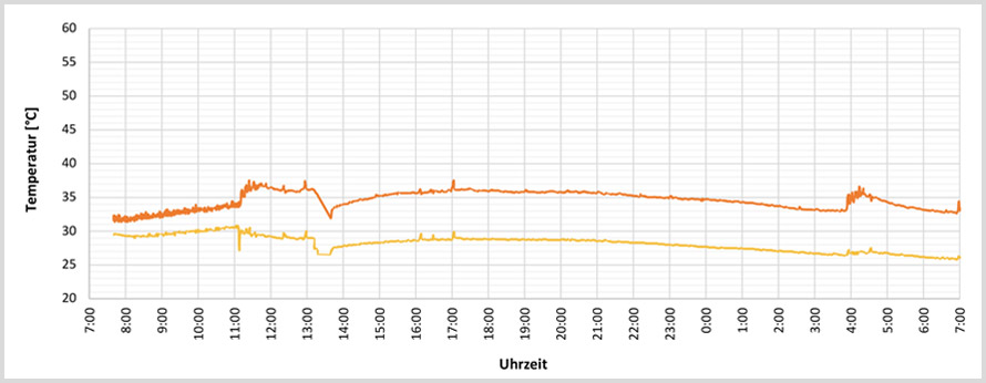
Control cabinet controller (free cooling)
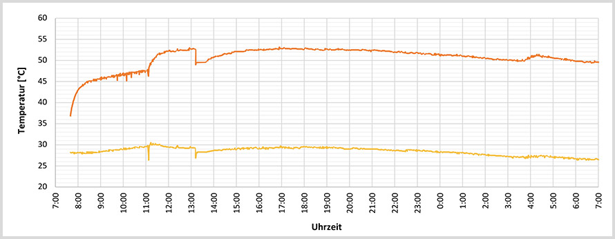
Figure 1: Chart showing the minimum and maximum temperatures in side the control cabinet over the course of a day without an AirBLOWER fan
Significant temperature reduction through air exchange
In the interest of sustainability, an alternative cooling concept was applied instead of increasing the cooling power, which makes more efficient use of energetically expensive air conditioning. For this purpose, both control cabinets were equipped with an AirBLOWER fan system, which can create an ordered circulation flow around the AirSTREAM wiring frame. This minimizes air layering and activates the entire surface of the control cabinet for heat dissipation to the environment. A second measurement was carried out after the conversion to confirm that this concept works, as shown in Figure 2. In control cabinet A (with cooling device), the AirBLOWER fan reduces the temperature stratification. The lower temperature level is raised by a maximum of 5 K, as the previously colder air layers mix with warmer air layers.
Control cabinet drive (cooler + AirBLOWER)
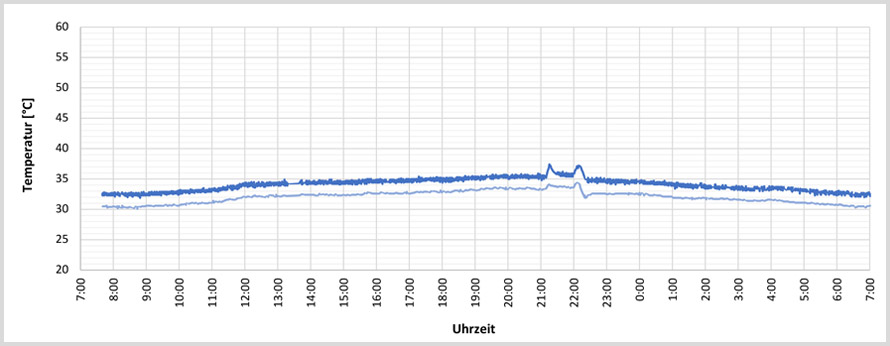
Control cabinet controller (AirBLOWER)
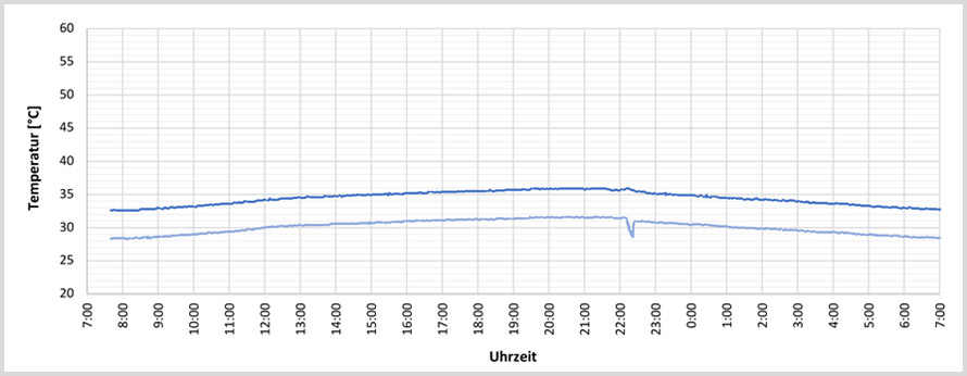
Figure 2: Daily progression of the minimum and maximum temperature inside the control cabinet with an AirBLOWER fan
The maximum temperature in control cabinet A remains below the limit of 40 °C. The focus in this configuration is on control cabinet S, where previously unacceptably high temperatures occurred. By using the AirBLOWER, the maximum temperature is reduced to 36 °C, which is 17 K below the previous temperature level. By homogenizing the air layers and increasing the air exchange between control cabinets A and S, all hotspots are eliminated and the risk of premature component failure is significantly reduced. The AirBLOWER can also be operated with temperature control using three temperature sensors placed in relevant areas of a control cabinet. Typically, there is a medium power requirement of 15 W. Compared to the active operation of a cooling device (typically > 500 W), air homogenization is far less energy-intensive.
This practical example shows how important it is to individually consider control cabinets, especially control cabinet combinations. In cooperation with the IGTE at the University of Stuttgart, Friedrich Lütze GmbH is continuously working on the further development and optimization of available cooling solutions, calculation models, and planning tools. In the future, the described problems should be identified in the planning phase of a system so that countermeasures can be taken early on. Resource conservation and operational safety can be achieved equally through norm-compliant but individual planning.
Authors:
Daniel Haag, M.Sc. (University of Stuttgart, Institute for Building Energy, Thermal Engineering and Energy Storage)
Michael Bautz, Product Manager Cabinet, Friedrich Lütze GmbH
Images:
Friedrich Lütze GmbH and iStock, Petmal